Domes and dry bulk
Geometrica works with plants and facilities at all altitudes to achieve the highest calibre of coordination between shipping and dry cargo handling and storage, writes Melanie Saxton of Geometrica.
Whether port side or high on a mountain, operations for mining, cement, fertilizer, power and many other industries require the stockpiling of large quantities of dry bulk materials. Storage of these raw materials has revolutionized over the decades with the advent of long span domes, horizontal silos and barrel vaults. Today’s technology allows for:
- internal cladding especially designed to minimize internal dust and protect structures from corrosive or combustible stockpiles; and
- external cladding that covers stockpiles and spares the ecosystem from emissions, runoff, and air pollutants. Neither brutal saltwater environments nor heavy snow loads are a match for Geometrica’s Freedomes®, which can span up to a remarkable 300 metres without internal columns or barriers.
Other challenging environments, such as those with typhoon- force wind loads or extremely uneven topography, also require careful design and remarkable structural strength and flexibility. Options include circular, conical, longitudinal and freestyle storage solutions. These structures, plus cylinders and geodesic domes, are ideal covers for stockpiles. The goal is to turn an often dusty or combustible stockyard into an environmentally sustainable system regardless of terrain or climate. Lightweight yet incredibly strong, Freedomes are prefabricated, containerized and shipped anywhere in the world. Regardless of geography, construction may proceed before, during or after material handling equipment is installed. Frequently, these all-terrain domes are built over existing live material stockpiles with minimal or no downtime.
Following are examples of durable storage structures in extreme locations around the world.
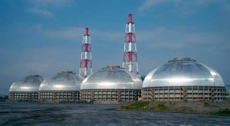
TAI POWER SILOS
Four beautiful examples of corrosion-resistant infrastructure are the immense coal storage silos at Hsin-Ta Fossil Power Station in Kaohsiung Hsien,Taiwan (see picture above). Gibsin Engineers specified aluminium cladding and galvanized steel for the structure. Due to Geometrica’s prefabrication and barcoding system of round tubular members, the bid was competitively priced. A team consisting of Geometrica,Triumstar International Co. Ltd. and Chien Yang Construction and Engineering Co. Ltd. (both from Taipei), was awarded the job.
The long span solution consisted of four 126m diameter concrete wall and metal dome covers built in a marine environment over an internal automated stacker/reclaimer system. Each unit would store 180,000 tonnes of coal in a live pile for a total of 720,000 tonnes. Geometrica handled design, manufacturing and technical assistance during installation and construction of the domes on site. All units were assembled using the ‘perimeter-in’ method of construction: the first nodes and tubes were set on the supporting concrete wall. Each of three to five tubes were joined to one node forming a ‘spider’. Each spider was then raised to the work front and tapped into place, creating rings around the base that grew one on top of the other until the whole skeleton was formed. Co-ordination with other trades was easy, as the area under the dome was free of obstacles. Neither scaffolding nor other special equipment were required, and the project was completed with a perfect safety record.
Turnover of the domes and testing of the first silo started approximately 16 months after start of construction. Today the Taiwan Power Company produces electric power in a clean and safe environment for surrounding communities.
EL BROCAL
El Brocal, compared to Tai Power, is an extreme opposite example of a setting. Far, far away from saltwater, the mining facility sits 14,200 feet above sea level in the Andes — one of the highest-altitude cities in the world. But whether portside or mountainside, a concern for the environment is a priority. The mine’s rugged landscape required protection from dust generated by mining copper ore and also transporting it to and from storage. As Peru’s largest publicly traded precious metals mining company, El Brocal fulfilled its commitment to preserving the environment with the architecture of its new storage building in Cerro de Pasco in central-western Peru.
The new storage structure was to be built within a constrained space, which meant that copper ore must be delivered via a tripper conveyor suspended along the length of the building’s apex. Therefore, the building’s shape had to support wind, live and material loads efficiently. It also needed a structure strong enough to support the weight of the conveyor equipment, as well as the vibrations and impacts created by the conveyed copper ore. Furthermore, even in the constrained space, El Brocal management mandated that construction take place with minimal interruption to its nearby mining facilities.
UREA STORAGE PORTSIDE
In another quayside project, Grupo CICE, a diversified logistics and transportation company, called Geometrica about its need to store urea as it arrived at the port of Veracruz (see picture below). When exposed to humidity, this extremely corrosive material attacks both aluminium and galvanized steel. Further, the coast of the Gulf of Mexico is one of the most corrosive atmospheres anywhere on earth, as industrial and marine exposures combine to torture metal. Up to 15,000 tonnes of urea needed to be stored while waiting for transport, and CICE needed a building that would withstand the corrosive attacks from inside and outside the building.
Geometrica’s solution for this challenging problem was a unique building of 52m internal clearance width, 18m clear height at the centre, and 120m length. The building’s lightweight skeleton is made of high- strength aluminium alloy and left exposed. But since urea can attack aluminium, the structure was protected by applying FRP cladding to its underside. The combination is perfect, with each material exposed only to conditions they resist: the aluminium structure is resistant to the corrosive atmosphere, and the polymer cladding resists urea attack, and prevents it from attacking the structure.
Construction took place quickly. Half-arches were assembled on the ground and lifted onto place with two light cranes. The whole construction process took four months. CICE’s general manager on site, Cesar Zamora, said of Geometrica “Excellent quality, service, and products. One hundred per cent recommendable.”
DUST DEFEATED IN ESCONDIDA
Freedomes may also be used to close-off existing, open ended storage structures in the most efficient manner, as done at the Escondida mine in Chile. Geometrica designed and manufactured the end for a 100m span vault built several years earlier. The vault had open ends, through which dust continued to escape until the 99m span Geometrica Freedome was installed (see picture above).
Geometrica has built some of the largest, highest and longest industrial domes in the world. The question is, “What can Geometrica do for you?”
PIRS domes do more than protect the environment
Concrete domes are highly effective storage systems, as they not only protect the environment from potentially harmful products, but they also protect the stored commodities from
destructive elements such as moisture and condensation.
INTRODUCTION
The environmental debates that have raged since the Rio and Copenhagen conferences show clearly that environmental laws must be reinforced — and further laws created — to protect the environment.
In many countries, there is a glaring absence of rules about the storage of materials, and people can just store what they want, where they want.
Domes help to protect the environment because they are hermetically sealed, insulated and waterproof (Figure 1). Products — such as fertilizers, cement, alumina and fly ash — can be stored easily, protecting the environment, while other materials like sugar and cereals are protected against contamination during their storage time.
ADVANTAGES
Cost effectiveness
Domes remain among the most cost-effective storage infrastructures, and represent one of the more competitive solutions for the storage of large volumes of bulk material. Operation, maintenance, conservation and energy costs are kept to a strict minimum.
Rapidity in construction
Once the airform is inflated, all the work is carried out inside the dome. Consequently, the stored products are unaffected by exterior environmental factors such as rain, wind, and daylight.
Optimization of the land
Domes minimize floor space while optimizing the volume. This means lower cost per tonne of storage.
Reclaiming
The bulk material enters the dome through openings positioned on the roof and is then reclaimed through one or more galleries located in the floor of the dome. Automatic reclaim systems such as mechanical screws, pneumatic systems or vibrating floors are perfectly well adapted to the dome.
Insulation
Domes are an ideal solution for the storage of bulk materials that are sensitive to temperature changes and humidity. The application of Vethane foam on the inner surface of the airform gives the dome the quality of being equivalent to a controlled atmosphere chamber. Condensation is practically eliminated inside the dome since the insulation of the dome will conserve a stable ambient temperature.The whole structure itself is perfectly adapted to the techniques of prolonged conservation of perishable products.
Waterproofing
A PVC membrane forms the exterior layer of PIRS’ domes and acts as the initial framework for the application of Vethane foam and shotcrete. Opposite to what is usually done in traditional construction, waterproofing is controlled at the very beginning of the process, once the airform is inflated. This membrane, added to the Vethane foam, ensures that water will never leak inside the dome and spoil the product.
Domes are an ideal solution for the storage of sensitive bulk materials.
CONCLUSION
PIRS concrete domes have proven their efficiency in protecting the environment and products against temperature and humidity. The filling and reclaiming systems, including operation and maintenance, are usually cheaper for domes than many other solutions. There are other factors that must be considered: the cost of the land, especially in a port (Figure 1 — see ‘PIRS SAS builds fertilizer terminal in the Port of Riga in Latvia’ on p84 of the November 2013 issue of Dry Cargo International) knowing that the domes will use less space than flat storage, for example. The time of execution can save financial costs and the operation can start earlier.
Domes are an innovative solution that are capable of bringing advantages in terms of product conservation, insulation, operation and maintenance costs. As a storage solution, they can help ensure maximum waterproofing and are a strong and durable solution for storage.
Safe silo storage of coal
Chris Geijs and Jaap P.J. Ruijgrok of ESI Eurosilo BV, the Netherlands, review fire protection in coal silos with the Eurosilo® system.
INTRODUCTION
With a history of over 40 years and a track record of more than 125 units built around the world, ESI Eurosilo is a leading engineering and contracting company in enclosed storage and handling systems. Proven silo storage solutions for coal fired power stations are in operation in a growing number of places around the world. FGD gypsum (a byproduct of the flue-gas desulfurization process), limestone, fly-ash and coal can be stored in silos with the proven Eurosilo® system. Enclosed storage of coal is based on a core flow silo system and meets with today’s stringent environmental and fire safety regulations, while providing the smallest possible footprint. Approximately one- third of space is used, compared to longitudinal and circular storage configurations. The Eurosilo® system offers storage capacities up to 125,000m3 per unit. A recent example of coal storage is the commissioning of two 100,000m3 silos at Lünen power plant for the Trianel Cooperation, Germany.
EUROSILO® SYSTEM WORKING PRINCIPLE
A core flow system is used for the storage of coal. During the filling process, the product enters the silo through a hopper mounted in the center of the roof and ends up in the telescopic chute. From here, the product can freely drop down towards the auger frame, located at the top surface of the stored bulk material. Two augers convey the material towards the silo wall. At this point, a sensor is activated, allowing the overhead bridge and suspended auger frame to rotate towards free space and distribute a new segment of bulk material.
This process continues for a complete layer of 360°. The winch system (located at the overhead bridge) hoists the auger frame one predetermined step after completing a full rotation. This cycle can be repeated until the silo is completely filled with bulk material.
During the discharge process, vibration devices, called Uncoalers, initiate a core flow in the middle of the silo to extract the bulk material. The overhead bridge and suspended auger frame rotate in a continuous counterclockwise direction, while one of the augers digs into the bulk material and transports the product towards the core flow in the centre of the silo. After a full rotation, the auger frame is lowered one step.This process continues until the silo is completely emptied. The Eurosilo® system also has the flexibility of simultaneous filling and reclaiming.
SELF-HEATING OF COAL DURING STORAGE
Self-heating of materials means the onset of an exothermic chemical reaction and a subsequent temperature rise within the combustible material, without the action of an additional ignition source. Generally, self-heating is supposed to occur when the rate of heat production exceeds the heat loss. When exposed to the atmosphere, nearly all types of coal show signs of self- heating, which results in a decrease of calorific value. Spontaneous combustion ultimately occurs when the heat build- up due to the right amount of oxygen is present over a longer period of time.
Limiting airflow (and thus oxygen) can be an effective way to reduce the possibility of self-heating. Storage time can be prolonged and calorific value will be preserved.A variety of methods can be used to reduce air entrainment in a stored pile of coal :
reduction of the exposed pile surface; minimization of water percolation into the pile (water creates channels, allowing increased airflow in a later stage); reduction of segregation during handling; and compression of the coal, reducing the voids in between the particles.
Storage of coal in a Eurosilo® takes advantage of all the mentioned entrainment reduction methods. The exposed area for a coal silo is significantly smaller, compared to A-frame type configurations or circular storage.
Enclosed storage in a silo protects the coal from rain. On top of that, spraying of the exposed surface to reduce dust emission is not required, thereby further reducing the percolation of water. The controlled method of stacking layers with the auger system ensures a minimum of segregation compared to the conventional chevron stacking method, which is used for most storage configurations. Layer stacking also establishes an optimal and evenly distributed compression of the stored bulk material.
Research by BAM [1] on self-heating in large coal silos shows that the chemical process is drastically reduced due to the relative small exposed surface and the evenly compressed bulk material. As a result of the absence of oxygen in the lower layers, the hot spots tend to originate just below the coal surface.
These hot spots can be reclaimed first due to the FILO (First in, last out) principle of the auger system, as explained earlier. It can be concluded that FILO reclaiming is favoured for this type of storage configuration! Multiple existing Eurosilo® coal storage projects confirm these research results. The Vattenfall Tiefstack project (two silos) has been storing coal for over fifteen years now [2].The Salmisaari power plant in Helsinki (four underground silos) even stores the coal up to six months without significant problems.
EUROSILO® FIRE PREVENTION SYSTEMS
Eurosilo® coal silos are equipped with multiple types of monitoring equipment to detect hot spots in an early stage. The filling and reclaiming mechanism is always right on top of the bulk material surface and rotates within the silo. This enables the system to do continuous monitoring of the entire stored bulk material surface.
Sensors continuously observe the amount of methane, carbon monoxide and oxygen in the air. Potential hot spots will develop close to the surface as mentioned earlier. The released CO can be spotted in an early stage and is indicated on a map to the operator. Measuring carbon monoxide over temperature is strongly preferred as detection method for self-heating in coal storage piles due to its advanced warning period.
Methane, carbon monoxide and oxygen sensors are also present in the basement and at the overhead bridge. Depending on the amount of CO (ppm), monitoring can be intensified, preventive actions can be taken, or the hot spot can be reclaimed from the silo.
All the ingoing bulk material during filling is monitored temperature wise. Bulk material in excess of 55 C° (104 °F) is rejected, according to IMSBC-code [3].
Stated CO values refer to the IMSBC code [3]. All the ingoing bulk material during filling is monitored temperature wise. According to IMSBC, bulk material below 55°C can be stored in the silo.The operator gets an alarm for bulk material in excess of this temperature, resulting in intensified monitoring. When the temperature exceeds 70°C, the arriving coal shouldn’t be stored in the silo.
Besides continuous monitoring, active airflow prevention is also part of the Eurosilo® fire system. The hoppers in the bottom of the silo are a potential entry point for air. By installing a slide valve underneath the reclaiming openings, air penetration is reduced to a minimum.
EUROSILO® FIRE SUPPRESSION SYSTEMS
All coal silos are equipped with a Nitrogen-purging system, enabling operators to purge the whole, or just a section of the silo, thus enabling longer trouble-free storage periods. The piping for this system is embedded in a layer of gravel at the bottom of the silo and covers the whole surface.
The reclaiming hoppers, being a potential entry point for air, can also be purged with nitrogen separately. A nitrogen evaporator outside the silo is able to make a direct connection to a truck with liquid nitrogen. This system has proven to be very efficient [4].
At upper bridge level, gel sprayers are present to cover specific parts of the coal surface with a layer of FIRESORB® gel [5] in case of a self-heating emergency. These sprayers are fed by a gel station, located in the roof gantry. The gel prevents the coal from having contact with the air and cools the coal down as well.
A spraying system is installed above the heat resistant conveyor belt in the basement of the silo to cool down heated coal.
FIRE AT MOORBURG POWER PLANT A recent example of self- heating in coal storage is the circular storage configuration at the new Vattenfall power plant in Hamburg- Moorburg.
Raised CO-values were found in one of the domes, caused by self-heating [6]. Further investigation showed increased temperatures up to 70°C for various locations in the stored coal. As a result, around 50,000 tonnes of coal were carried towards the Wedel power plant. It would have been better to deal with the cause of the problem in the first place, instead of having to struggle with the consequences.
An ounce of prevention is worth a pound of cure. Inherent to circular storage is the large exposed area and the impossibility to do continuous CO-monitoring of the entire surface. Subsequently, hot spots will not be detected in an early stage and drastic measures will be required to solve the problem. On top of this, nitrogen purging is not a possibility for this type of storage configuration, leaving carrying away of all the stored bulk material as the only viable solution.
DISCUSSION
The Eurosilo® fire protection system combines limited access of oxygen to the coal due to the FILO stacking process with an extensive monitoring and suppression system to minimize the risk of a fire hazard. Comparing fire risk assessments of coal storage silos using this protection system, with those of storage in A-frame type configurations or circular dome storage, the mammoth silos will be favourable in many cases.
Chris Geijs (MSc Eng.) R&D manager and Jaap Ruijgrok (MSc Eng.) Managing Director of ESI Eurosilo B.V.
REFERENCES
[1] BAM Report on the prediction of the hazard of self-ignition in a storage silo for black coal Reference Number : II.2-329/06, April 2006
[2] C.Rosner, H.Röpell, HKW Tiefstack, Hamburg,Vattenfall Europe Wärme AG. Erfahrungen mit Silobränden im HKW Tiefstack,VGB Fachtagung 2010
[3] IMSBC-code, International Maritime Solid Bulk Cargoes code section 4 (fire protection)
[4] DMT, Inertisierungstest Kohlesilos Tiefstack, Juli 1997
[5] Degussa creasorb,Technical information and Instructions for the handling of FIRESORB®
[6] Moorburg storage dome fire - http://www.nonstopnews.de/ meldung/17634
Rubb: ideal port of call for those needing storage facilities
A manufacturer of relocatable engineered fabric structures is leading the way in the space race when it comes to providing storage solutions to the ports and marine sectors.
Rubb was the first port of call when Sunderland City Council required a new cargo facility at Hendon Docks in the UK. A versatile storage area was needed to help continue the development of the Port of Sunderland’s cargo handling facilities. In conjunction with SGW Construction, Rubb erected a 24m span × 65m long BVE cargo handling and storage facility with 7.65m sidewalls. The design and quality of the structure provided a safe and pleasant cargo storage solution. Rubb’s innovative customized structures ensure safe and secure access to the storage area, while the translucent roof provides a natural source of light. The internal clear-span steel framework allows the maximum use of available storage space.
Rubb also helped a port building project grow at the Port of Belfast. Rubb began working with Belfast Harbour Commissioners back in 2001 to ensure that their ever changing and ever expanding storage requirements were met as use of the port developed. The first Belfast Harbour warehouse storage facility was erected in 2001 at the head of the dockside area. It measures 24m span × 45m. In 2005 an additional building measuring 24m span × 65m long was erected directly adjacent to the existing harbour structure. In 2003 a much larger harbour storage building measuring 45m span × 175m was installed at a different location on the dockside and in 2004 this was extended to 217.5m in length. In 2005 the Rubb design team was given a brief to erect the largest possible building on the remaining land on this site. Careful consideration had to be given to the design because of restrictions created by the nearby dockside traffic. However, a 32m span × 60m harbour storage facility was installed, maximizing all possible space available, taking the storage area constructed by Rubb to a massive 14,347m2.
Meanwhile the Port of Workington offers high-quality storage facilities in the form of two relocatable Rubb constructed ports buildings. The ports structures measure 25m span × 32m in length and 25m span × 61m in length. These port facilities provide storage space for animal feed and protection from the elements and light. The design features a split storage capability. As this part of the west coast of England is susceptible to severe winds and rain, the storage systems were constructed on top of 4m retaining walls. The walls consist of a steel support structure complete with pre-stressed concrete infill panels, which allow for quick and easy construction. This method provides a fully sealed facility to prevent water ingress and also allows for internal retaining walls to be built for different storage needs. The client required a dark covered port storage facility as animal feed needs to be protected from light, however the translucent PVC material used on other Rubb ports projects provides a brighter working environment without the need for windows.
More recently Rubb has been providing facilities to the renewable energy, alternative fuels and biomass power marketplace. Rubb’s bioenergy storage structures can provide customers with the ideal environment for the processing, handling and storage of bulk materials. Its technical team can offer expertise and experience in the design, engineering and construction of large scale biomass building projects at port locations. Ongoing product development of biomass energy facilities ensures that Rubb continues to meet its clients’ demands. Experience and a flexible approach enables us to efficiently overcome challenges, meet changing needs and requirements quickly and cost effectively.
Rubb Buildings Ltd was also tasked with designing, manufacturing and erecting two crane liftable buildings to cover offshore pile clusters in a marine environment. The two marine manufacturing covers from Rubb’s new BLE series for Harland and Wolff feature spans of 30m and each measure 35m in length. To increase the overall internal apex height of the manufacturing bays to 20.2m, H&W asked Rubb to use a 7.3m high wall constructed out of 40ft containers as the building’s foundation. A custom designed supporting frame was created to hold the containers together and act as the fixing base for the Rubb BLE structures.
The buildings are designed with reinforced base beams and anchor brackets so they can be easily lifted from their container foundations and moved to one side. This allows the client to then crane lift materials into the space within the foundation frames for various operations. The building roof is replaced to protect employees and materials from the elements. Each gable end of both paint and blast facilities includes a pedestrian door and a 4m x 4m roller shutter door for equipment access.
Ten advantages of selecting Rubb structures
- all Rubb products are suitable for ports/logistics/warehousing type applications. The flexibility of a Rubb structure means it can be used to house a wide variety of goods;
- Rubb’s port storage solutions offer a number of advantages to our clients. Its climate controlled warehouses provide dehumidified storage environments, while our bulk storage facilities are ideally suited for storage of materials under the strenuous conditions of a marine environment;
- Rubb storage buildings offer marine terminals a solution that allows for maximum flexibility with respect to multiple handling methods and configurations;
- relocating and re-using these buildings to suit the changing needs of a busy port is easy and cost effective;
- additional buildings can be added as required;
- the PVC cladding will not corrode in a marine environment and allows the structure to accept differential settlement without the need for expensive pile foundations. These same features give Rubb an advantage when it comes to preventing leaky roofs;
- Rubb structures provide large column free spaces, illuminated by natural light through a translucent roof. This provides a safer and more cost effective working environment than other traditional warehouse buildings;
- Rubb buildings can be designed, delivered and erected within eight weeks;
- these semi-permanent structures are designed to stand for as long as the client requires. All steel used in a Rubb building is hot dip galvanized to strengthen the frame and provide a durable maintenance free facility. The high quality PVC coated fabric cladding has been proven to last in excess of 30 years;
- Rubb’s unique custom solutions enable it to handle all types of projects, large and small, from designing, manufacturing and constructing large new plants to extending existing facilities.
Rubb Buildings Ltd was established in 1977 and is based in Gateshead, Tyne and Wear. The Rubb Group also has office and manufacturing facilities in Norway and the USA.
Cement storage and onward forwarding from Motril in Granada, Spain
The project began when the company Hormigones Domingo Giménez decided that it needed to get maximum processing efficiency at its plant in the Port of Motril in Granada, Spain, writes Eduardo Heras Villoldo of Claudius Peters Ibérica, S.A.. This rectangular-shaped plant stores cement that is brought into the port by ship.
Claudius Peters Ibérica designed an optimum solution — flat silos. These silos had to meet two pre-conditions: they had to fit the rectangular surface, and meet the height limit of approximately 12m.
SILOS
The three silos measure 20m × 20m each, with a height of 12m and a total capacity of approximately 3 × 5,000 tonnes.
In traditional cement silos, there is always a significant loss of height, due to the need to place trucks below the silo for loading. One of the main advantages of this new silo design is that it uses the height from the ground level to store material, which leads to a significant gain in the silo capacity and the possibility of lower height in silos in places where needed to meet regulations.
SHIP UNLOADING
Ship unloading is achieved by a Siwertell machine (which uses a hydraulic and mechanical system of screw conveyors) to two tank trucks. Cement unloading is achieved at a rate of 500tph (tonnes per hour). From the dockside, the cement is transported to the silos.
FEEDING THE SILOS
The cement is carried by tank trucks and, with their own compressors, is pneumatically conveyed to four inlet ducts for each silo that homogeneously spread the cement that is to be stored.
Another proposal, which was not pursued, was transporting the cement to the silos pneumatically, using a Claudius Peters pump and compressor.
EQUIPMENT IN THE SILO ROOF
In the roof of each silo, there is: v a filter bunker, for dedusting the air from the feeding system
and the silo discharge; v pressure valves, with two level detectors; v four material inlets; and v horizontal and vertical doors with safety protection.
FLUIDIZATION
Each silo is divided into four quadrants. Each of these has three fluidization sectors, that are further divided into subsectors. During normal operation these are fluidized via a programme in automatic cycles and by rotary blowers during residual discharge.
SILO EMPTYING AND TRUCK LOADING
Each silo is emptied radially, towards the centre, using four outputs through 90°, positioned in a 3.3m × 3.3m chimney in the centre of each silo.
The material in each output is dosed by a pneumatic flow control gate. It is then sent to a feed box where a vertical screw conveyor collects material at ground level and raises it 14 metres before loading it into a 12m-long aeroslide. This aeroslide conveys the material, by a fan at one of the silos. It falls into a stationary loading device with a wear cone system. From here, it is loaded into tank trucks that are weighed on the scale underneath.
Trucks are loaded automatically with the required weight. The loading speed is 250–300tph, and does not generate any dust. The system allows for the simultaneous feeding of the silo from 12 trucks, and at the same time is able to load three trucks from the silo. The silos began operation in August 2008, once all commissioning was complete and the performance guarantees were achieved to the full satisfaction of the customer. At that time, it was a new design for the storage and emptying of silos for this type of product.
ADVANTAGES
This silo design has the following advantages:
- maximum exploitation of the storage from the ground level;
- lowest height required for a given silo capacity;
- costs of civil and installation work are greatly reduced;
- low energy consumption;
- easy and automatic running;
- low maintenance costs;
- versatility to position truck loading operations where the
- customer wants; and
- the silo surface can be adjusted easily to the ground or land available.
DemcoTECH: servicing the international dry bulk cargo industry
As opposed to liquid bulk, containers and other general cargo, dry bulk cargo is mostly transported in loose form, determining to a major extent the storage and transport technology employed at the quay, in the terminal and at other locations before onward transportation, says DemcoTECH Engineering General Manager, Paul van de Vyver.
Johannesburg, South Africa-based DemcoTECH has been responsible for designing and installing bulk materials storage and handling facilities for a growing international client base. Its comprehensive suite of systems and technologies ranges from troughed and pipe conveyors through to moving head systems, trippers, stackers, sampling plants, tipplers, storage facilities and bulk material silos.
“Conveying cargo in loose form can potentially contaminate the environment and, vice versa, the material can itself be contaminated by the surroundings. With a clean environment now increasingly a major focus area of regulation and social pressure groups, we design and install equipment that complies with stringent environmental and safety requirements. In addition, we offer a range of enclosed conveying technologies such as our troughed AeroConveyorsTM, pipe conveyors and pneumatic conveying systems,” adds van de Vyver.
DemcoTECH counts amongst its clients major mining houses, cement producers and terminal operators.
“Projects we have been responsible for range from a clinker silo at NPC Cimpor’s Simuma Plant in KwaZulu-Natal, South Africa, through to materials handling engineering and support services for one of the world’s largest iron ore distribution centre projects in Malaysia ”
DemcoTECH was the materials handling engineering-service company on Vale’s project to establish a regional iron ore distribution centre in Lumut, Perak, Malaysia. The distribution centre includes an ore storage yard and a marine terminal which will be capable of handling more than 60 million metric tonnes per year, receiving iron ore from Vale's mines in Brazil for distribution to customers across the Asia Pacific region. DemcoTECH also provided operational readiness services, including the preparation of operational and maintenance manuals and training modules. Work started on the facility in 2010 and the first two 400,000dwt vessels carrying ore to the Malaysian Terminal were off-loaded early in 2014.
“DemcoTECH has in the past also been contracted by South Africa's major shipping and logistics company, Grindrod Terminals, for projects at both its Maydon Wharf and Richards Bay terminals in South Africa’s KwaZulu-Natal province,” notes van de Vyver.
Responsible for the design and installation of the materials handling portion of the expansion to Grindrod’s multi product terminal at Richards Bay, DemcoTECH provided all the materials handling plant to convey various materials, but mainly rock phosphate and coal, from the three Richards Bay terminal sites.
The original system conveyed material from terminal conveyors to feed a single warehouse, with the expansion extending the system to feed two other warehouses.
For Grindrod’s Maydon Wharf terminal in Durban, DemcoTECH supplied a mobile ship offloading facility, together with a new warehouse distribution system for the fertilizer storage facility. The system replaced a trucking system and comprised four 400tph (tonnes per hour) mobile, tyre-mounted conveyors which are stationed on the jetty at locations to suit the ship docking arrangements. Once the ships have been offloaded, the conveyors feed the fertilizer to a central pivoting and retractable boom conveyor. The existing warehouses were modified to incorporate reversible, multi-point discharge shuttle conveyors that feed individual bays. Fully sequenced automatic starting and stopping of the systems ensures a seamless operation, and the ability to handle different types and grades of fertilizer.
“For cement producers, we offer a full range of services from silo design and construction through to materials handling systems,” says van de Vyver.
Working in a joint venture with Kantey & Templer Engineers of South Africa, DemcoTECH design and built a 40,000-tonne, multi-discharge clinker silo with associated feed and discharge materials handling plant at NPC Cimpor’s Simuma Plant.
Kantey & Templer was responsible for the silo’s civil and structural design, engineering and project execution, and DemcoTECH for the materials handling elements of the project, including the project execution of the system.
The new silo, positioned alongside the existing silo, handles hot clinker up to 205 oC, and features a clinker steel pan feed system that can feed clinker to either the existing or the new silo.
The clinker silo consists of a 40,000-tonne free capacity, reinforced, pre-stressed structure with a 30m internal diameter and 55m height. The clinker silo has two reclaiming tunnels and a precast concrete conical roof.
The silo receives clinker from the kiln via a silo feed Aumund steel pan conveyor and discharges at 250tph onto two reclaim conveyor belts with heat resistant belting. The clinker is then fed to either the existing plant or a new rail loading system.
Located in environmentally sensitive Oribi Gorge area of KwaZulu-Natal, the silo’s design controls dust emissions from the plant to well below regulatory requirements.