By Bernd Mann, iSAM AG
At first look, train unloading seems to be a relatively simple process not requiring advanced sensor or automation systems. There are various types of railcars which have either bottom- or side-mounted flaps for unloading but most operators still use rotary dumpers. The latter rely usually on an indexer arm to position the cars precisely in the dumper barrel.
Many train unload stations today are entirely manual with the performance depending on the individual operator. Other stations use automation to a certain degree but require permanent supervision or don’t work at the maximum possible
throughput due to limitations in the control system. Depending on the mechanical design of the train unloader
there are several areas which need to be addressed to allow a ‘true’ automation without compromising on machine safety and performance.
- train position measurement and car/locomotive detection;
- dumper pit feeder control; and
- indexer control (where applicable). The following article describes these systems in more detail including real-world challenges and benefits.
TRAIN POSITION MEASUREMENT AND CAR/LOCOMOTIVE DETECTION Especially when using rotary dumpers, it is necessary to have a system that safely detects the locomotive and the cars, so that the locomotive is not rotated. Also, in the case of bottom or side flaps, have precise knowledge of the position of the train can avoid spillage, and enables the optimized control of the train unloading process.
iSAM uses 2D laser sensors mounted above the train just outside the dumper cell. The lasers have a scanning angle of 180° and can therefore detect the locomotive or the cars in front of and inside the dumper cell.
To speed up the positioning of the train and optimize the indexer movement, the system can be extended by additional sensors in the entry- and run-out section of the train dumper.
At the time of entering the dumper, the engine driver gets an indication based on feedback from the scanner where to stop the locomotive. After stopping, the dumper operator initiates the automatic sequence and the indexer starts an initial gap hunt to automatically push the first two cars into the dumper station without the need to interact with the engine driver.
After dumping the last cars, the laser scanners detect the locomotive but no car behind it and stop the indexing sequence. The engine driver is informed by the machine operator that the train has been finished and removes the train.
The graphic above provides an overview of the sensor arrangement including the two additional laser sensors in front and behind the dumper station at a twin car dumper in Canada.
DUMPER PIT FEEDER CONTROL
Once the car has been dumped, the material is usually removed from the dumper pit via vibro-feeders which transfer the material onto a conveyor belt. In many installations, these feeders are already equipped with variable frequency drives (VFDs); however, a proper manual control requires constant attention by the operator. Frequently, the material flow through the feeders is not homogeneous and when one feeder runs empty, subsequent cars are directly dumped on the belts damaging the equipment in the long run. At the same time, other parts of the dumper pit still hold too much material to dump the next car and therefore delay the train.
To overcome these problems, a radar level measurement can be installed looking down into the bunker above each hopper. Radar level sensors are very robust and reliable especially in dusty environments and provide fast feedback regarding the bunker level. The connection to the control system is usually via Profibus/Profibus PA.
The control system receives an individual level signal for each hopper and can use this to control the vibro- feeders. If the level of a hopper drops below a pre- defined value (e.g. level of the grizzly), the PLC stops the relevant vibro-feeder to ensure no feeder is running empty during dumping. An outer control loop adjust the total output of the vibro- feeders which is especially important when blending materials. The graphic, left, provides an overview of the sensor arrangement at a twin car dumper with eight feeders.
NDEXER CONTROL
When an indexer is used to move the train, usually the indexer arm is pre-positioned based on the known length of the cars and the position of the dumper cell. However, as train brakes do not always work perfectly, there can be positioning inaccuracies and the train’s behaviour can change during the unloading process. Therefore, some fine-positioning is required in most situations which is either done manually or by using photocells on the indexer. Both systems require an early slow-down of the indexer and therefore prolong the cycle time.
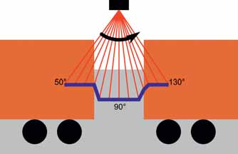
To overcome these limitations iSAM has developed a precise, real-time gap position measurement system. This exactly determines the position of the gap between two rail cars in front of the train unloading station. It provides a safe and robust measurement which ensures an exact and fast positioning of the train indexer arm. The system consists out of a 2D laser scanner, a PC with control software to process the scanner measurement data and a PLC program that will control the train indexer arm with respect to the train gap measurement.
The drawing above shows the sensor setup as installed on an iron ore dumper in Port Hedland, Australia.
Being mounted directly on the indexer the system is not affected by inaccuracies in the absolute indexer position measurement. However the high vibration levels and the very demanding, dusty and hot environment required the use of a special mil-spec housing with vibration control.
SUMMARY
Modern control systems using 2D laser scanning for train and indexer positioning allow a fast and consistent automatic operation of train unloading stations. When properly designed these systems reliably prevent the accidental dumping of mid-train or end-train locomotives and ensure an operator- independent performance.
In addition, an optimized flow control from the dumper pit using radar level sensors shortens the dumping cycle and avoids dumping material directly on the belts through an empty hopper. Compared to entirely or partly manual systems a reduction of the cycle time by 50% or more can be achieved. However even when compared with already optimized, conventional sensor systems performance gains of more than 8% have been demonstrated.
ISAM: THE COMPANY
Technology and automation provider to the global transport and heavy industry with 90+ employees (including subsidiaries) in Germany, Australia, North America and Eastern Europe specializing in advanced control systems.
iSAM delivers the full range of products and services for advanced automation of port operations and bulk material handling. Since 1983 a team of specialists from the fields of engineering, IT and physicists have been working with experienced business administrators as well as process and project managers to provide intelligent solutions for the tasks of today and the challenges of tomorrow.
iSAM offers turnkey solutions for new automation projects as well as the upgrading of existing equipment including project management, electrical engineering and commissioning.
ABOUT THE AUTHOR
Bernd Mann Chief Officer Development, Design and Technology Background Bernd Mann initially studied particle and laser physics at the University of Bonn before joining iSAM in 1993 and being appointed as CTO in 2002.
He is a member of the Transport and the Industry Committee, as well as a delegate to the General Assembly of the Chamber of Industry and Commerce for Essen, Muelheim and Oberhausen.
Mann is greatly involved in research and development of advanced automation systems in the industrial sector of bulk material handling and port automation. His experiences are based on the realization of many automation projects for bulk terminals all over the world.